-> HathiTrust Digital Library Site; Link to First page of article.
I removed non-Cripple Creek text from the source, and I added images from my collection as source had none. I also added in info from a referenced text.
for Railways.—With an Actual Example.
A good deal has been written about "Electric Motors Under Steam Railway Conditions," but in the majority of cases the investigations have been carried along on well-known street railway lines, the investigators seeming to lack the dash and education in expedients which is so necessary in carrying out new problems.
Below I present the result of my investigation of what at first appeared to be a very difficult railway problem, i. e., the electrical equipment of the Florence & Cripple Creek Railway. If the work is carried out on the lines indicated, it will result in a saving over present earnings more than sufficient to pay desirable interest on the bonds and stock of the road; if any one will take the trouble to figure the same out on street railway or third-rail lines, they will probably find it to be a losing proposition.
Herewith I hand you some preliminary figures and information concerning the cost and advantages of an electrical equipment for your railway. They are based on the following data I have been provided with:
In changing from steam to electric motors, assuming you are hauling the equivalent of 40 loads from Florence to Cripple Creek per day, together with your passenger trains, by using electric motors, the following expenses would be avoided:
|
|||||||||||||||||||||||||||||||||||||||||||||||||||||
| Saving with electrical equipment per day | $228.78 | ||||||||||||||||||||||||||||||||||||||||||||||||||||
In addition to this, other savings of very considerable importance would be made, which are impossible to estimate.
The electric locomotive would have swivel trucks, with a wheel base of about 5½ feet, and would curve much easier than your locomotives on your many miles of 32 degree curves. The probabilities are that one-third of the power now absorbed by your locomotives with their 11 feet 9 inch driver wheel base, would be avoided, with a corresponding reduction in the wear and strain on the curved track.
As the weight of the electric would be very much less than the steam locomotives, the destructive effect of the track and the maintenance of way, would be more than correspondingly decreased. The rule is that this effect increases with the square of the weight (up to the elastic limit) which in your case is sometimes exceeded, as evidenced by bent rails, etc.
Another great saving would be effected in the rolling stock. Steam locomotives do their work by a succession of jerks, first on one side and then on the other. This effect is very pronounced on such roads as that up Pike's Peak; the tendency to rack and weaken the cars is much greater than where electric motors are used, as their strain upon the cars is without impulse or shock.
While your locomotives are doubtless the best steam ones that have been designed for severe mountain work, they are very inefficient machines, and there seems to be little chance to improve on them, as the manufacturers have already strained points in every direction to increase their force and efficiency.
The boiler pressure, which is now 160 lbs., is really close to the danger line. The weight which is more than 50 tons, could not be increased without injury to the track. The leverage could not be increased by decreasing the size of the drivers, as they are now but 36 inches in diameter. The boiler could not be lengthened without increasing the wheel base, which your sharp curves would not permit.
Notwithstanding all of this weight and strained engineering, the locomotives do not develop at the draw bar on your curves over 120 horse power at a speed of five miles per hour, cutting off at half stroke.
That most popular standard street railway motor known as G. E. 800, weighs about 1,600 pounds, with 33 inch wheels; at a speed of 11 miles per hour, it exerts a horizontal effort of 800 pounds, properly geared; it is consequently capable at a speed of 5 miles per hour of giving a draw bar pull about equal to its own weight.
I would propose in place of the steam locomotives to use electric locomotives of about double their capacity, so that one motor would handle 10 loads up to the 4 per cent. grades. After due consideration I have concluded the following installation would about fill the bill:
Although the equipment would be quite a departure from ordinary street railway practice, I am not straining any engineering possibilities, or proposing any plans which would not be approved by the best available talent, while they might be questioned by engineers of less experience.
The steam power to generate the current would be located at the coal banks near Florence. The current would be transmitted to duplicate converters, located at the telegraph stations on the right of way along the railway, at a potential of 20,000 volts. Each standard direct current locomotive would have four 600-volt 100 horse power motors.
The trolley wires would be supplied with direct current on the Henry three-wire commutative system (see U. S. Patent 545, 158, of Aug. 27, 1895). One side would have a difference of potential of 800 volts, and the other of 1,200. The motors would receive current from either or both sides, i. e., at 800, 1,200 or 2,000 volts pressure, and be further regulated by connecting them in series or in parallel. In no case, however, would any one of the motors receive current at over 600 volts potential (this being the common trolley railway pressure).
To prevent racing when the armatures are connected in series, the field magnets would be separately excited by being connected in series with a rheostat to the low voltage side. Owing to the high pressure on the mains and working conductors the losses would be less than on the ordinary street railway circuits. While the losses in regulating the motors would be about nihil at any speed up to the maximum, it is thought that these savings would more than compensate for the losses inherent in the transformers.
The trolley wires and three-phase transmission wires would be carried on the same pole line. The method of suspension would be the combination diagonal span and bracket construction. (See The Electrical Engineer, March 31, 1897, page 348.)
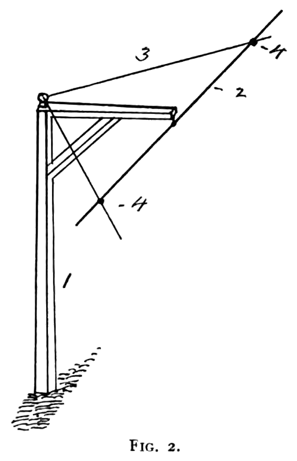
RECENTLY I have been making an estimate on the cost of constructing a long electric railroad in the mountains. In scheming to cut down the expense, it occurred to me that a very considerable saving could be made by using a slight modification of the writer's previously described diagonal methods of support.
The plan shown in the below sketch requires but one-quarter of the number of poles that the ordinary span construction does, or but one-half the number required by the bracket construction. In addition, the span wires may serve as feeders and also act as stays for such pull-offs as may be required on long curves.
The span has other advantages; among them, the liability of the poles being broken down by landslides, falling rocks, runaway teams, etc., is reduced in proportion to their number.
In the sketches, Fig. 1 is a plan view of the line construction; Fig 2 shows an ordinary bracket pole. The meaning of the numbers are: #1 represents the ordinary bracket poles, #2 is the Trolley wire, #3 is the diagonal span wire and feeder, and #4 is the insulating hanger.
The cost of the complete installation would be about as follows:
| 50 poles per mile, including brackets, insulators and setting at $5 each, total for 40 miles | $10,000 | |
| For 3-phase current, 120 miles of No. 1, hard drawn insulated copper wire at 13c. per lb.; total | $28,628 | |
| For trolley circuit, 40 miles of 000 wire, and 40 miles No. 1 | $28,628 | |
| Stringing wire and bonding track at $100 per mile | $4,000 | |
| Line construction complete | $71,256 | |
| 7 locomotives at $ 6,000 each | $42,000 | |
| 4 400-k. w. dynamos, at $20 per k. w. | $32,000 | |
| Converters | $40,000 | |
| 4 500-h.-p. stationary engines at $5,000 | $20,000 | |
| 4 500-h.-p. water tube boilers, at $12 per h. p. | $24,000 | |
| Electrical incidentals | $5,000 | |
| Building power house and setting machinery | $15,744 | |
Total |
$250,000 | |
In figuring on the capacity of the machinery, we have aimed to have one of the 500-horse-power units in reserve; the balance would be quite sufficient to carry the maximum load. No estimate is made of the value of the 12 steam locomotives, which could be disposed of.
This electric plant could be used to advantage in operating the proposed Florence Southern road, without much additional expense, as current can be distributed from the central point with much less loss than from the ends of the line. Besides these there need be no additional expense for station attendance.
The distribution system could also be amplified and used to great advantage in furnishing the mining camps with light and power. It would not require, comparatively speaking, much more of an outlay to deliver 1,000 electrical horse power at the mines, which would doubtless sell at very high prices, where it could be used to operate pumps, hoisters, etc.


