-> My Collection; PDF File. Or, link to first page on Hathi Trust Digital Library website.
(pages 501-502)
During the summer of 1902, the management of the Portland Gold Mining Company decided that the high expense of surface tramming at the No. 2 shaft could, by installation of proper rock-handling machinery, be materially reduced. To this end it devolved upon the writer to erect the present system of skips, cars, and conveyors, which, after four months' trial, has proved a conspicuous success.
The design of the system is a combination of ideas furnished by Mr. J. R. Finlay, manager; Mr. Kurie, surveyor; Mr. A. E. Johnson, master mechanic, and the writer, constructing engineer, all of the Portland company.
Combined with the advantage of decreasing the cost of surface tramming, it was found feasible to increase the capacity of the shaft, to furnish new and extensive waste dumping-ground, and to allow extra sorting outside the ore-house.
The increase in the shaft capacity was effected by the introduction of self-dumping skips. A rubber-belt conveyor and link-belt pan-conveyor allowed wide extension of dumping-ground on either side of the shaft, and side-dumping cars reduced the surface trammers from nine men to four.
The Self-Dumping Skips.—The skips are of the Chapin Michigan type, but essentially modified. The aim was to produce a skip which would hold double the load, in rock, of the double-deck cages previously in use, but would not increase the total load on the hoisting engine.
The extra weight of rock in the skip load was to be played off against the lighter construction of the skips. This was satisfactorily accomplished. The skips weigh each about 2,800 lb.; the load of each is 6,000 lb.; therefore the total weight is about 8,800 lb., which corresponds closely to the weight of the old double-deck cages, with cars carrying about 3,000 lb. of rock. Thus, with reference to load, with no alteration in hoisting power, a given shaft capacity was doubled.
The main departures of the Portland from the Chapin skips are in the head construction, including the method of hanging, and the safety-device; in the guide-shoes and in the dumping hooks.
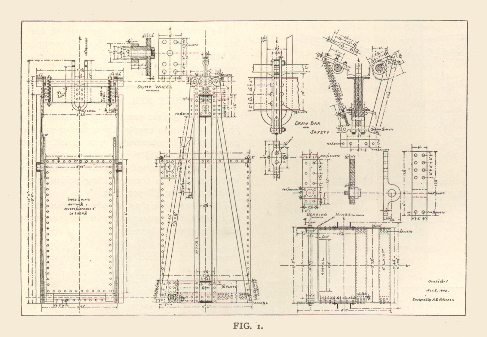
Fig. 1 is from the working drawing. The method of attaching the cable by the U-bolt about the cast-iron centerpiece is neat and strong. The safety-device is simple and inexpensive. The position of the hooks near the side of the box is to afford support for a side shield of No. 10 sheet steel to prevent rock from escaping sideways into the shaft as the skips are loaded. The skip-box is made removable from the cage portion of the skips by split hinges.
It has been proved, however, rarely necessary to remove the boxes, a removable platform being provided which is hung inside the boxes to the depth of about 3½ ft., when men are lowered and hoisted. Most of the timbers handled through this shaft are lowered on a wooden cage running in the pipe compartment. For handling men the skips are protected by a sheet-steel hood bolted to the flat cable.
On reaching the surface, the dump-wheels on the skip-boxes engage a double track (upper and under) of 2½ in. by 3/8-in. angle iron, riveted to ¼-in. steel plates, which are fastened in turn to a wooden framework built out from the head-frame. The dumping tracks are arranged so as to allow the passage of three-ton side-dump cars in front of the shaft. The skips dump their loads directly into these cars. Two, sometimes three, cars are used.
One is pulled by a mule on a curved track, on a trestle, to the ore-house, situated about 70 ft. in front of the shaft. Here the ore is dumped on a grizzly, by throwing a trip. The load slides out automatically.
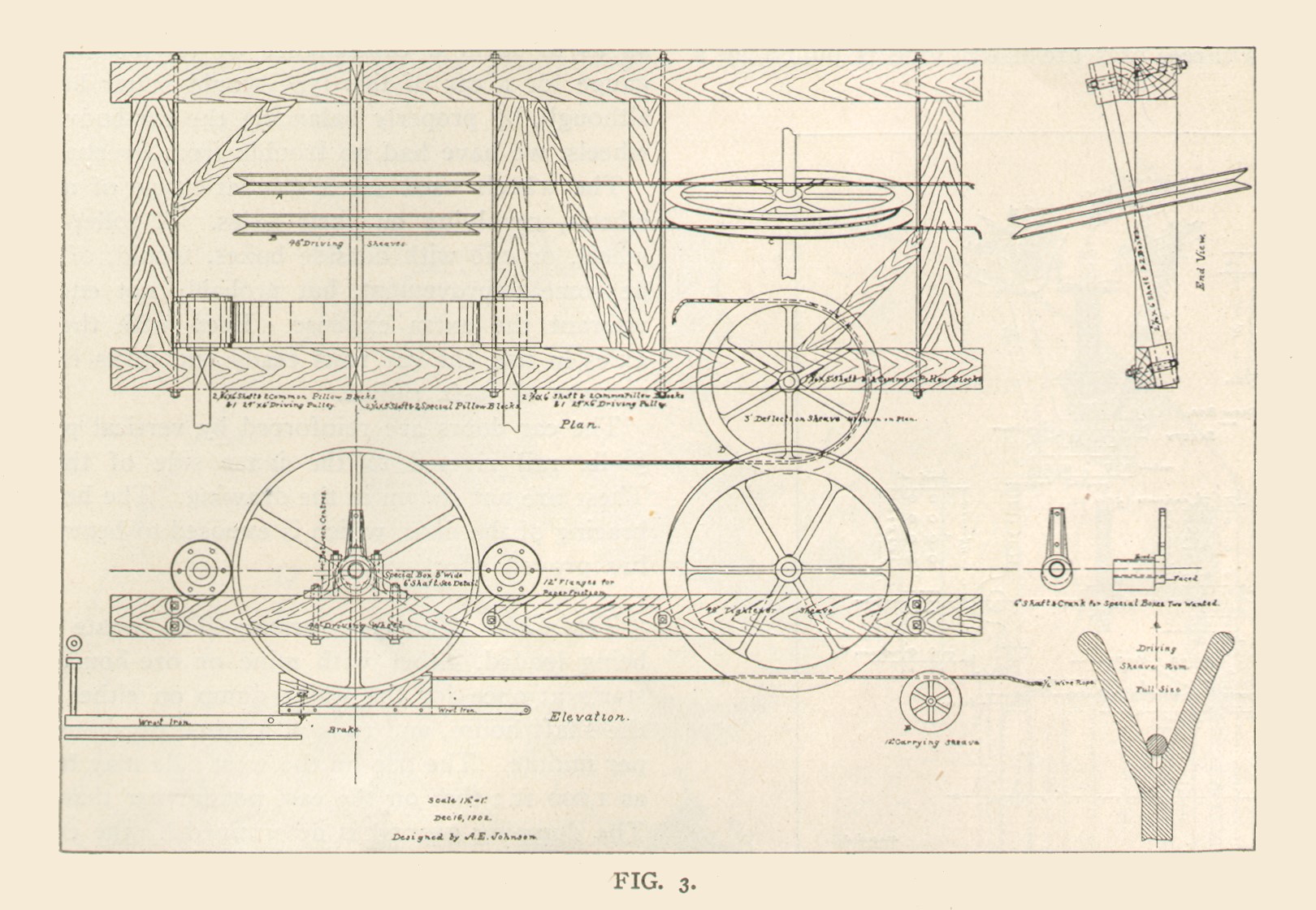
One, sometimes two, cars of exactly the same pattern as the ore-car are used to pull out the waste. These cars are moved by a cable haulage system, outlined in Fig. 3. The waste-cars also handle ore-house waste from a bin just outside the shaft house.
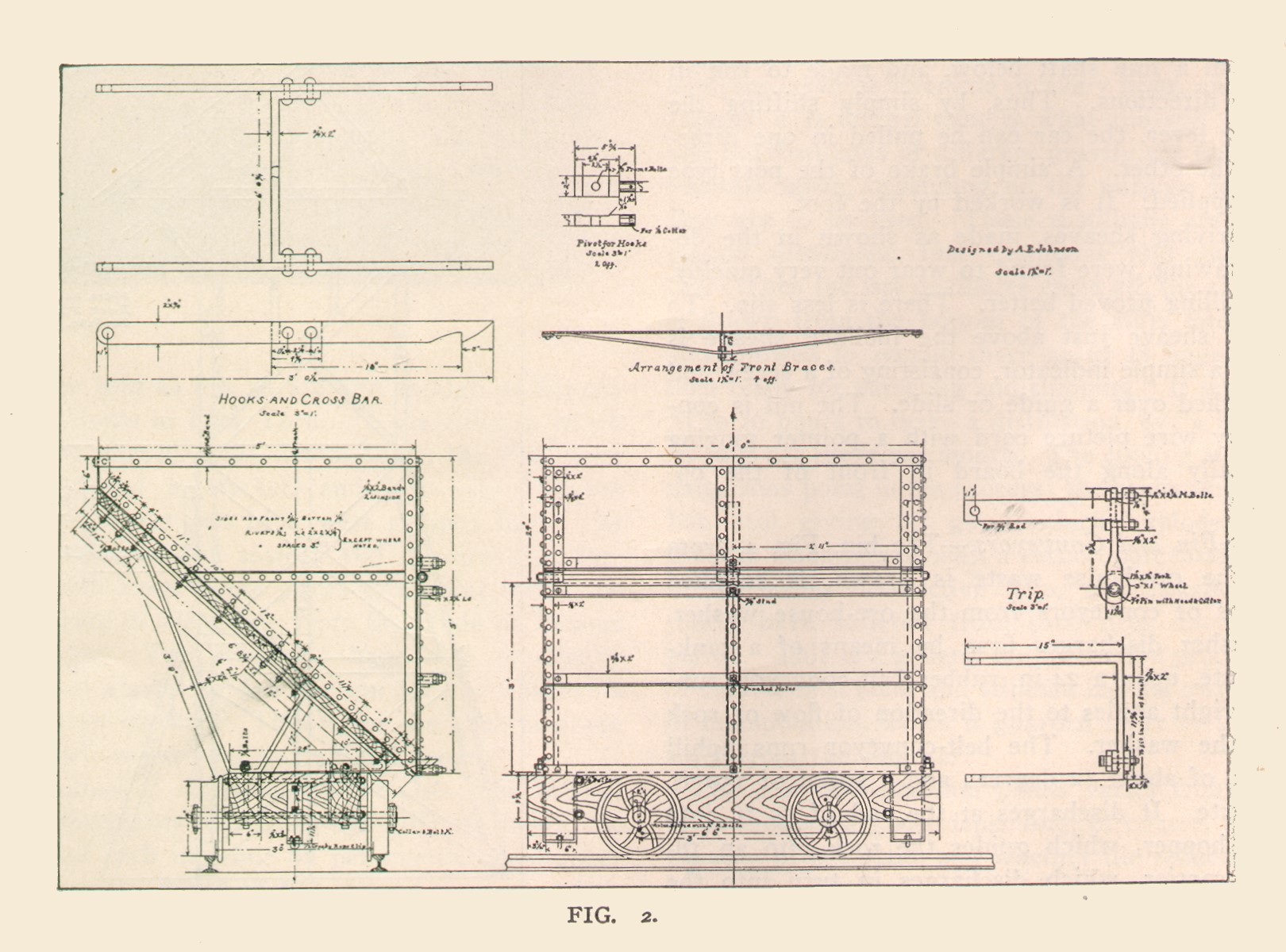
The Portland Side-Dumping Cars.—The side-dumping car, Fig. 2, is, like the skip, based upon the Chapin design, but is even a more radical departure from the original. It is practically a new design, only the general form of the Chapin car being retained.
The Chapin has a wooden framework and braces beneath; the Portland, a framework of wrought iron. The Portland thus presents a simpler and, the writer believes, a neater appearance. The 30-in. gauge makes the car rather narrow for its height.
It was thought best not to set the car lower on the trucks, since, in that event, the wheels on the discharge side of the car could not be easily removed for greasing, and the car could not throw its load so effectively out and away from the track. This shooting out of the load is assisted by a lip of ¼ in. by 8-in. tank-steel (not shown in the drawing), attached so as to form a continuance of the bottom.
The gauge for a car of this type would better be 36 in., although, by properly balancing the car-body on the wheels, we have had no trouble from overturning.
The wheels used are a standard type of mine-car wheels, revolving on their axles. A roller-bearing wheel, or one with outside boxes, would, of course, be some improvement, but probably not enough to warrant the extra expense. Even with the rough axles in use, the car runs easily and turns easily on a curve of 30-ft. radius.
The car doors are reinforced by vertical pieces of 30-lb. rail riveted to the inner side of the door. These are not shown in the drawing. The horizontal bracing of the door, which is exposed to heavy shock, has proved effective.
The Cable Haulage System.—The waste car on being loaded, either with mine or ore-house waste, starts at once for the waste dump on either side of the shaft house, and runs at a speed of about 900 ft. per minute. The trip on the west side may be as far as 1,000 ft.; that on the east not farther than 600 ft.
The dumping ground is determined by the condition of the dump. The waste track was first started on a trestle from 10 to 20 ft. in height. This trestle is now filled in and the dumping proceeds along the down-hill edge of the old dump. The track is moved over when slices of about four feet in width are laid on.
The cable which pulls the cars is 1½ in. extra flexible plow-steel wire. It is carried, on a straight track, by wooden rollers of 5 in. diameter and 12 in. face, spaced 18 ft. apart. The roller shafts are 7/8-in. round iron unturned. The roller bearings are 2-in. plank notched.
The cable is carried around curves on cast-iron sheaves 8 in diameter by 2 in. width set horizontally about 1 in. inside of the path of the draw-bracket on the car. The cable is attached to this draw-bracket by ½-in. Crosby patent wire-rope clips, the extra cable being secured on a reel which is bolted to the bottom of one of the cars.
Thus as the track is changed the length of the cable can be altered without splicing. At the two ends of the track the cable passes around 36-in. horizontal rope-filled sheaves. It returns on 12-in. cast-iron sheaves, lubricated by grease-cups discharging into hollow axles. The return cable is placed back and away from the dumping track, and the sheaves are supported mostly on posts. At curves they are placed horizontally; elsewhere, vertically.
The cable haulage, Fig. 3, has been modified slightly to improve its efficiency, but in the main it retains the features of the illustration. The paper friction-wheels are now mounted with bearings on either side of the 8 in by 4 ft. cast-iron friction-wheel, which makes a little firmer construction. The two eccentric boxes of the iron friction-wheel are connected by ½ in. by 2 in. wrought iron bent over the top. This forms a hoop, which is connected, by a rod and a lever mounted on a shaft, to the operating lever on the other end of the shaft. The paper friction-wheel shafts are belted by long quarter-turn belts from a line shaft below, and made to run in opposite directions.
Thus, by simply shifting the operating lever, the car can be pulled in one direction or the other. A simple brake of the post type is also applied. It is worked by the foot.
The driving sheaves, made as shown in the detailed drawing, were found to wear out very quickly. A rope filling proved better. There is less slip. To the 3-ft. sheave just above the inclined sheave is attached a simple indicator, consisting of a screw and nut, notched over a guide or slide. The nut is connected by wire picture cord with a pointer moving horizontally along the board in front of the operator.
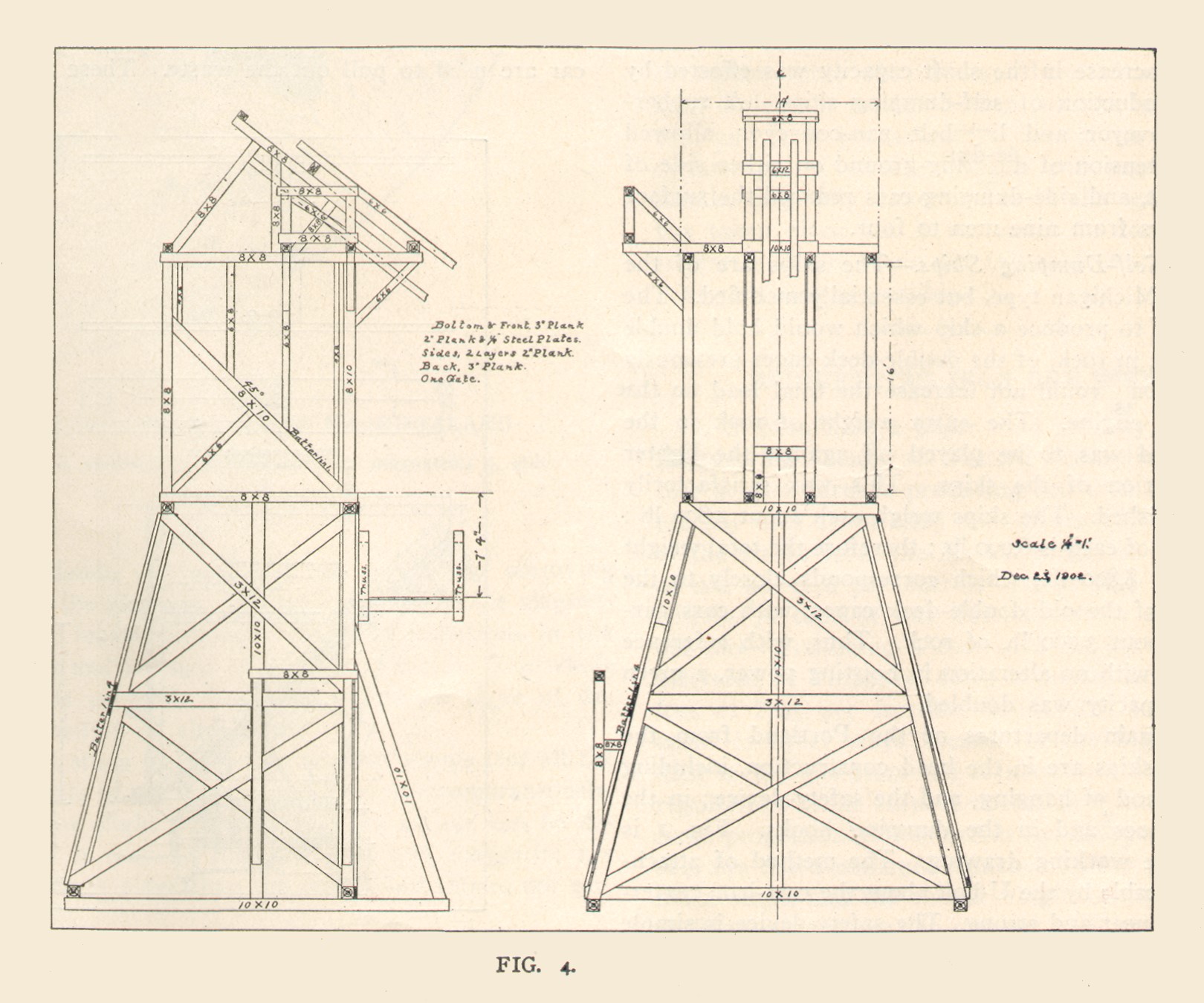
Waste-Bin and Conveyors.—The bin, Fig. 4, from which the ore-house waste is drawn, is supplied by means of conveyors from the ore-house washer. The washer discharges first, by means of a tank-steel chute, upon a 24-in. rubber belt-conveyor, running at right angles to the direction of flow of rock out of the washer.
The belt-conveyor runs uphill at a rise of about 12 degrees and a speed of 150 ft. per minute. It discharges at the end of 35 ft. into a small hopper, which guides the rock into an 18-in. pan carrier, which discharges in turn into the waste-bin.
In experimenting with the belt-conveyor, it was discovered that, with a speed exceeding 150 ft. per minute, the rock had considerable tendency to roll back, the rolling back just about equaling the upward travel of the belt. This rolling is, of course, very detrimental to the life of the belt, since the material handled is as large as 16 in. diameter at times.
The belt of the conveyor is 4-ply, with 3-22-in. rubber cover. It runs upon flat rollers furnished by the Link Belt Machinery Company of Chicago. The rollers are spaced 4 ft. The end pulleys are 24 in. in diameter by 26 in. face.
The rock is prevented from falling off the sides of the belt by 2 in. by 8 in. plank inclined toward the belt. The plank is adjustable for slight variations in position of the belt sideways, and for wear of the edges.
The Link Belt Machinery Company pan-conveyor is of the standard pattern. It runs on carry and return tracks connected by truss construction. The plans as regards woodwork were somewhat modified to suit existing conditions of the ground. The truss superstructure is supported on well-braced bents every 16 ft., except for the last two stringer-lengths next to the bin. Here a simple king-post truss was employed.
This conveyor, like the belt-conveyor, is provided with side-guards of 2 in. by 8 in plank, but in this case non-adjustable. This was found to be very necessary, for otherwise the pans, which are 6 in. deep, would at times become overloaded and spill the rock upon the return portion of the conveyor beneath.
Then, as the return pans close together around the lower sprocket wheel, the rock would bend them. Also, except for the side guards, rock would endanger the driving mechanism over the bin.
The bin, Fig. 4, has a 10 in. by 10 in. timber, with upper edges protected by angle iron placed just below where the pan-conveyor discharge drops. Thus is formed a rock cushion upon which the rock drops, never injuring the steel bottom of the bin by its fall. The bin is more thoroughly braced than is shown in the drawing.
The bin gate is of ½-in. boiler plate, size 30 in. by 36 in. It is raised and lowered by a home-made air-lift and a valve designed by Mr. A. E. Johnson. The cylinder is made of 6-in. pipe bored out, with ordinary 6-in. pipe caps on either end. A simple piston and rod connected with the gate through an ordinary stuffing box and ½-in. pipe connections from the ends of the cylinder to the valve complete this simple but very clever and useful device.
The writer regrets that the time at his disposal has not permitted of furnishing drawings complete in regard to the present actual construction and a general sketch of the system.


